Inductor design characteristics are defined in terms of various parameters. Inductor winding is made of a conductor material which may be a single round wire or a unique multi-stranded conductor known as Litz wire. Litz wire has the main advantage of reduced skin effect. Inductor design characteristics are defined in terms of various parameters which are discussed in this technical article.
Recommended Reading
AAC Textbook Chapter 15 - Inductors
Understanding Inductor Designs for Converters
Copper Fill Factor
Inductor winding is made of a conductor material which may be a single round wire or a unique multi-stranded conductor known as Litz wire. Litz wire has the advantage of reduced skin effect. Let the cross-sectional area for the conductor be AC and say it is making N number of turns. Then, the total cross-section covered by the conductor is N AC.
Let the window size for the winding be AW which includes the area of the space between the conductors and the area covered by the insulation.
Conductor fill factor,
where VC is the volume occupied by the conductor and VW is the volume for the window.
Practically, FC is 0.3 for Litz wire and 0.5 to 0.6 for round conductors.
Let d be the diameter of the round conductor, then while the skin effect is negligible.
Winding Loss and Current Density
The winding loss due to the DC resistance of the conductor winding per unit conductor volume is given by the following expression:
Here, is the specific resistivity of the conductor. It can also be written as
where JC is the current density in the conductor.
If we want to express the power loss per unit window volume, then it can be written as,
If the skin effect is considered, the formula will be,
Now the following approximations are considered to make the design simpler and to derive the constraints’ equations for the design of the inductor.
Let the inductor L be carrying the worst-case current Im without saturating the core. This causes an operating core flux density at maximum value of Bm. It must be less than the flux density at saturation i.e. Bm < BSAT.
Copper Loss
We also know that resistivity of the conductor’s core is much lower than that of the resistivity of the air gap, so let the resistivity of the core be neglected:
[Equation 1]
It shows the relationship between the turns ratio and the air gap length which put a constraint on these parameters.
Resistance of Winding,
where ρ = resistivity of material for conductor; AC = conductor’s cross-sectional area; lWR=N lmeanT is the length of the wire where lmeanT is the mean length of the wire per turn.
Thus, [Equation 2]
This is also a constraint equation.
Another constraint equation according to the basic inductance equation is given below.
[Equation 3]
This relationship put the constraint on the design by proposing the relation between the turns ratio, N; area of the core, AC'; and the length of air gap, Ig.
The last constraint is according to the window size. Area of the window must be larger than the cumulative area occupied by the conductors, thus,
[Equation 4]
The overall summary of the constraints for the design of the filter inductor are,
In these constraints equations,
AC', AW, and lmean depend on the geometry of the core.
Im, Bm, μ0, L, FC, ρ and R are known parameters which are given according to the specification of the particular inductor.
The value of the number of turns N, length of air gap Ig, and the cross-sectional area of the conductor AC are all unknowns here.
One of the most obvious things about the design of the inductor is the choice of material. Inductor core is made up of various materials which shows different B-H curve. The temperature of the core rises due to eddy current losses especially when high frequencies are used in the converter. Thus, we generally use the laminated sheets or granulated iron in cases where iron must be used as the core material. The ferrites which have large thermal conductivity are also commonly used as core materials to limit eddy current losses. The inductor temperature is dependent on the convective and radiative transfer of heat. A prototype of the desired inductor should be operated at the rated values and the temperatures of it should be measured. If the temperature is excessively high or low, the design should be changed accordingly.
One of the most fundamental parts of inductor design is knowing the stored energy in the inductor. We know that the total flux linkage for the inductor is given by
[Equation 5]
B and JRMS depend on the selection of material while parameters FC, AC and AC' depend on the geometry of the winding and core. These given equations above relate all these mentioned parameters to the input parameters of the inductor: L,I and IRMS.
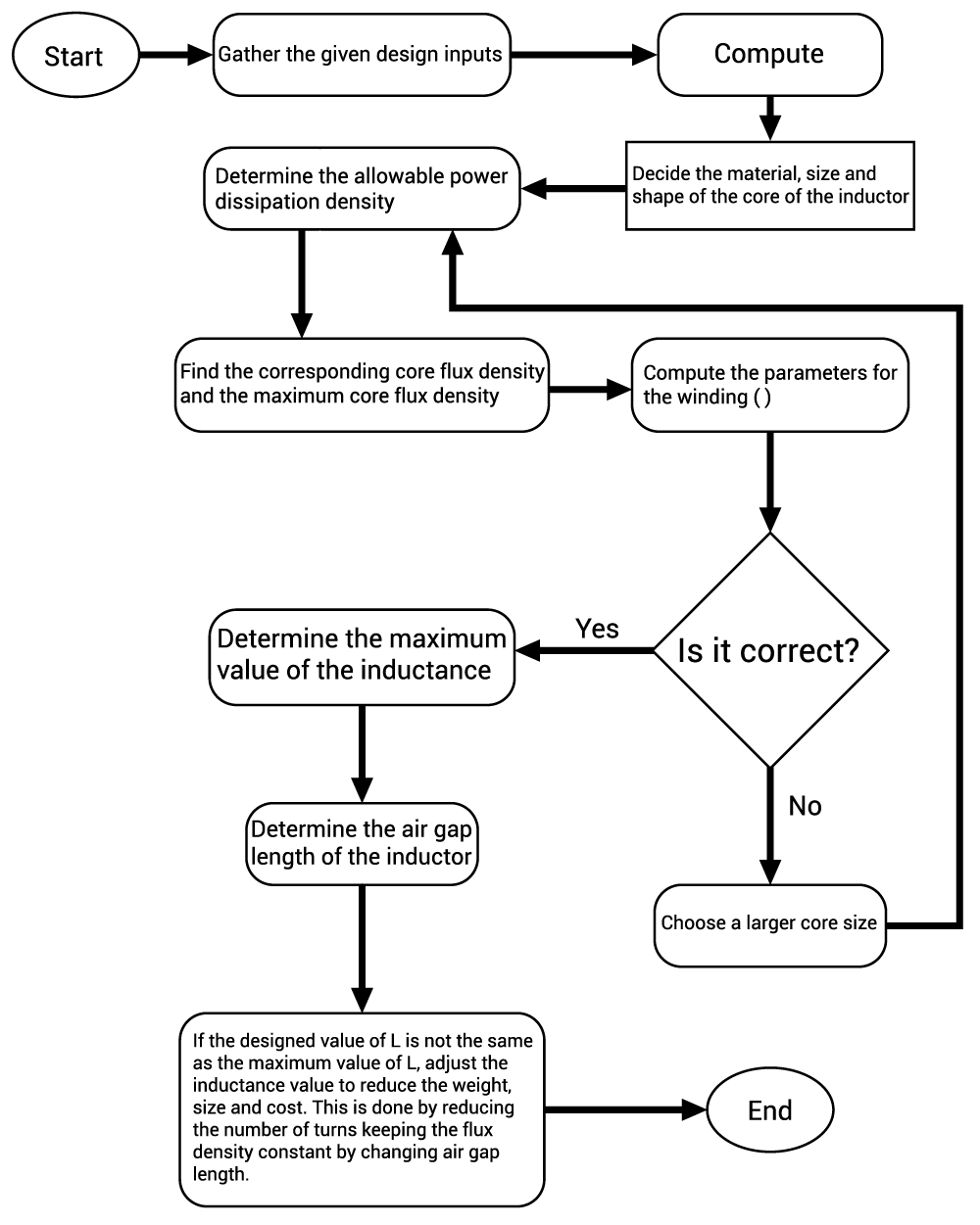
Now the step-by-step procedure is given for the design of inductor below. It is designed for the allowable temperature and power density of the inductor.
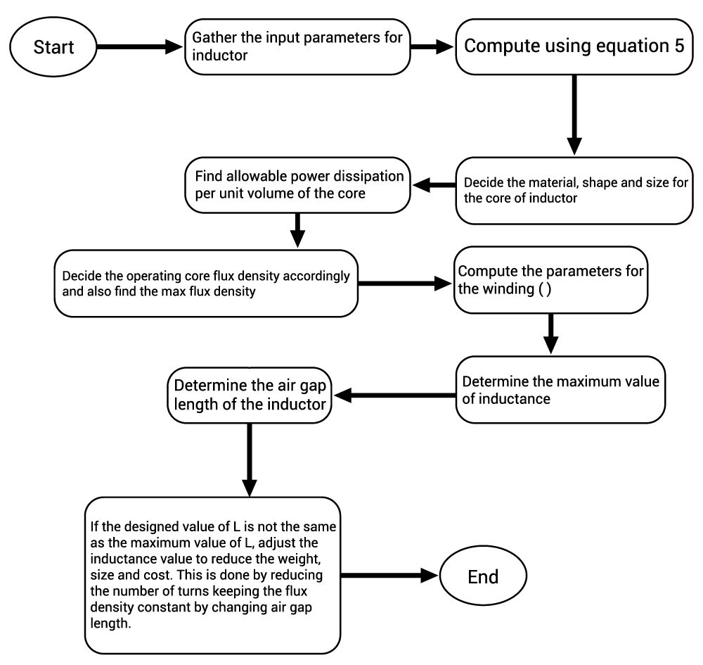
If the complete parameters for the core characteristics are not available, then we can find the proper values with the help of iteration. Initially, an estimated value of the current density JRMS ≈ 2 to 4 is considered. Also, the magnetic flux density can be found using the expected value of the core loss and finding the corresponding value of the operating flux density using the graph between core loss and B. Then core size can be decided based on Equation 5. The corresponding iterative process is shown below.