Introduction
Whether they are used for heating a reptile enclosure or an avian incubator, cooling a computer or a video game controller, switching an attic fan on and off, or for something else entirely, thermostats have many applications around the home and shop, and are surprisingly easy to build. The three major parts of a thermostat are the temperature sensor, the temperature comparator with an adjustable setpoint, and a control circuit for the attached heater, cooler, or fan. This article will provide details on the temperature sensor and the comparator, but because the external device being controlled (heater, cooler, fan, etc.) dictates the parameters of the controller circuit, it will not be included in this article.
Thermostats can be mechanical, electrical, electronic, or some combination of the three. Electronic thermostats can be built using discrete components, operational amplifiers, or microcontrollers, but as the title states, this article is about building a thermostat with the amazing PICAXE µC as the temperature comparator. The DS18B20 integrated circuit will be used as the temperature sensor.
Building and programming this circuit requires a modest background involving PICAXE microcontrollers, and if you find yourself underequipped, a review of some of these articles may be in order.
DS18B20
The temperature sensor selected for use with the PICAXE is the DS18B20 from Maxim Integrated, and is described fully in the datasheet. This project will use the TO-92 package, but if your requirements are for a surface mount device, the DS18B20 is also available in 8-pin SO and µSOP packages. Just make the adjustments to the pin numbers and, because the capabilities are identical for all three variants, you should have no problems.
The DS18B20 normally reads out in degrees Celsius, its range is from -55ºC to +125ºC, and its accuracy is specified to be +/-0.5ºC from -10ºC to +85ºC. It can provide either 9-bit or 12-bit resolution, and operates on 3.0V to 5.5V. Multiple DS18B20 devices may be operated on a single 3-wire buss, but this project will only use one sensor.
Circuit
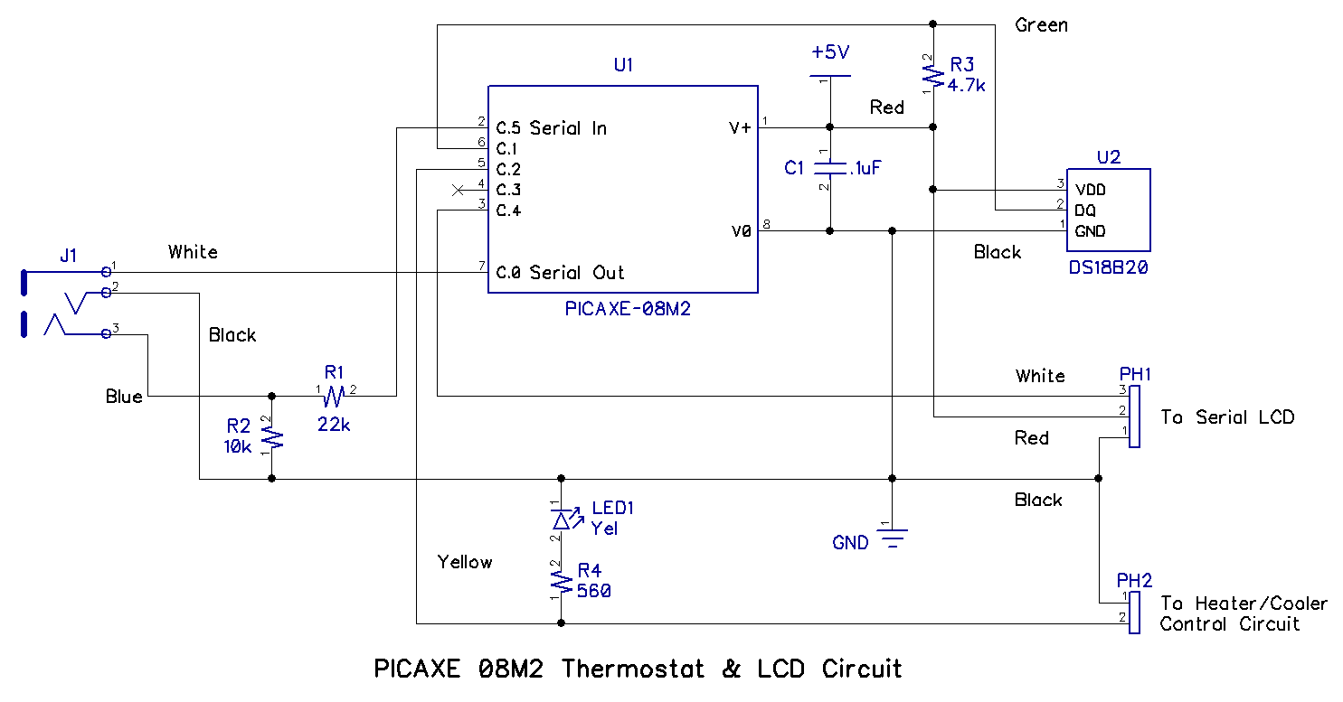
The circuit shematic for this project is shown below; it is relatively simple and is very similar to the design used in other PICAXE articles and projects by this author. Click the image for a larger version of the schematic.
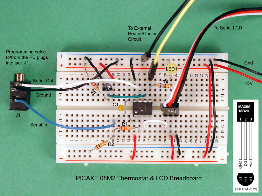
The photo below shows the solderless breadboard assembly of the circuit, and is electrically identical to the schematic diagram above. Click the image for a larger version of the photo.
Given the schematic diagram and the solderless breadboard photo, you should have very little trouble duplicating the assembly. The following notes should provide the answers to most questions you may have.
- The pinout diagram for the TO-92 version of the DS18B20 is shown in the photo. Be sure that you understand that the pinout diagram shows a bottom view of the device, but a top view is shown in the breadboard assembly.
- LED1 will light simultaneously with a power-on signal to the external heater/cooler control circuit. Note that the maximum available current from a single pin on the PICAXE is 20mA, and the current flow through R4 and LED1 is approximately 5mA. Therefore, no more than 15mA is available to the external heater/cooler control circuit.
- All wire colors on the schematic diagram correspond to the actual wire colors shown in the breadboard photo.
- All resistors are .25 watt, 5% tolerance.
- A regulated +5VDC power source is required; three AA alkaline batteries in series will suffice.
- The PICAXE programming interface is explained here.
- The serial LCD is explained here.
As usual, you should recheck all connections before proceeding further. By far, most problems with newly built breadboards are due to wiring errors.
Code
The code to operate the thermostat circuit is shown below.
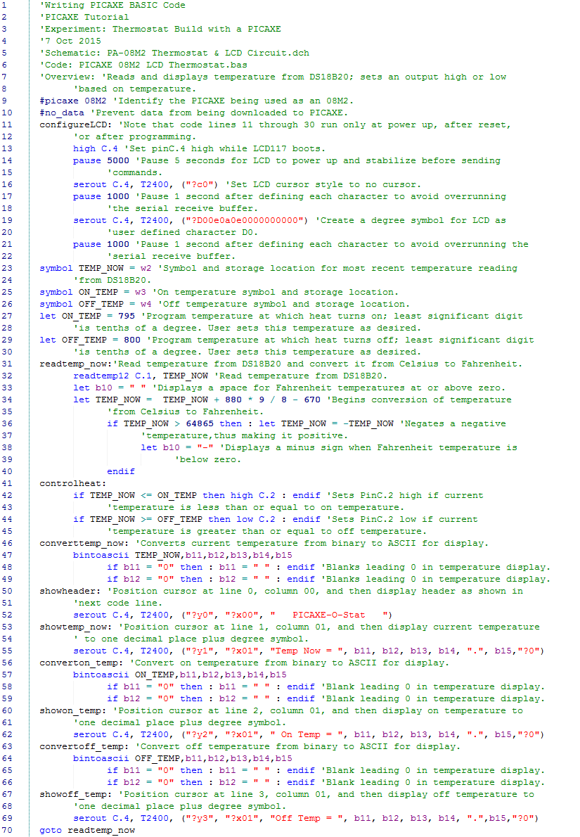
As you see, the code is well commented (in green text) and presents only a couple of new commands beyond those used in previous articles by this author.
- Lines 19 and 20 are used to create a new custom character in the serial controller for the LCD: a degree symbol (º). The instructions for how to create custom symbols pixel by pixel are contained here, but a far easier way is by using the clever program created by Paul Badger, and available at the last bullet under "Resources" here.
- Line 32 is the actual command for the PICAXE to read the temperature from the DS18B20. If you have read very much from the DS18B20 datasheet, you were probably expecting something a lot more complicated, but the folks at Revolution Education, makers of the PICAXE system, did the work for you. The readtemp12 command is discussed in PICAXE Manual 2.
Download the code, open it in PICAXE Editor 6 or the IDE of your choice, power up the breadboard circuit (You did double check all the connections, right?) and program the 08M2.
PICAXE_08M2_LCD_Thermostat.zip
Running the Code
After the code compiles and is programmed into the PICAXE 08M2, there will be a delay while the LCD is configured and boots, after which it should be similar to the photo below. If the temperature where you are isn't 78.5ºF, you should see your local ambient temperature displayed.
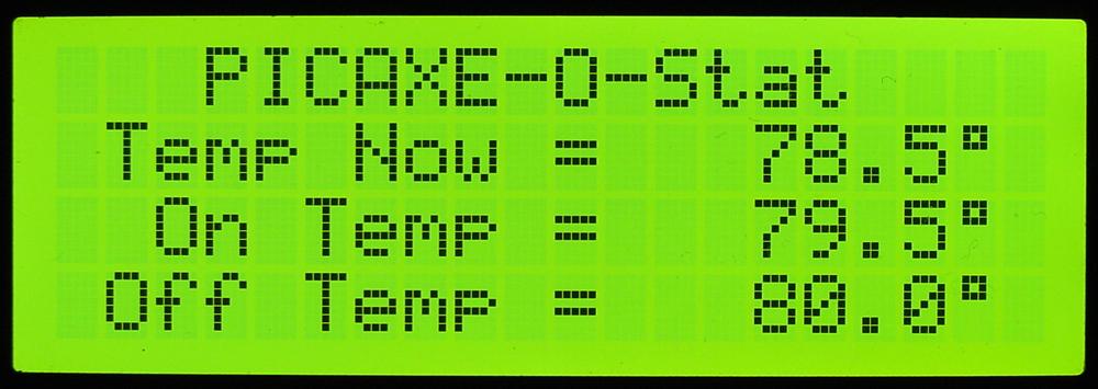
"But wait," you might say. "I thought the DS18B20 read out in Celcius, not Fahrenheit!" And you would be correct. However, lines 34 through 39 convert C to F; if you want Celcius, just modify the code to eliminate this conversion.
"What about the on and off setpoints? How do I change that?" Once again, the answer is in the code; just change lines 27 and 29 to whatever temperatures you want, and reprogram the PICAXE.
And did you notice that nice degree symbol after each temperature reading? That is the new custom character created in lines 19 and 20. To see the other custom characters in the serial adapter, turn the power off and on, which will cause the LCD to reboot, and show the boot screen below.
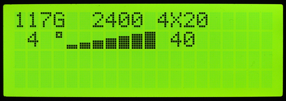
The eight custom characters are in the second line of the display: the degree symbol (º) followed by the seven vertical bars. All eight of those are in the non-volatile memory section of the serial controller, and will remain there until they are reprogrammed.
Final Thoughts
Adjust the setpoints to just below and just above the ambient temperature where you are. Then, blow your breath on the DS18B20 and watch the display register a higher temperature and turn off the yellow LED. Continue watching as the DS18B20 returns to ambient temperature and the yellow LED goes on.
Study the code, make changes in it, and test your changes. There is no better way to learn to write code than to...well, write code.
Have fun!
Give this project a try for yourself! Get the BOM.

