Curious about the "internet of things?" The info you need to get connected is provided here in easy-to-follow instructions.
What is the IoT?
The Internet of Things is nothing more than connecting "things" like appliances, cars, sensors of all types, and much more to the internet for the purpose of receiving and/or sending data from/to those "things." The data can simply be information such as whether a garage door is open or closed, or it can be control signals to open or close that garage door. Specialized web sites have been created to facilitate the interchange, storage, and/or display of this data; the project described in this article will make use one of those sites: Thingspeak.
Project Summary
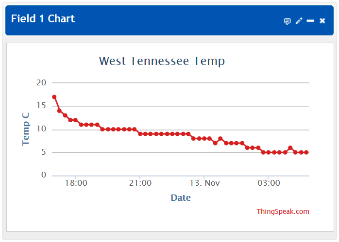
By following the instructions in this article, you will be able to use a DS18B20 integrated circuit to measure temperature, a PICAXE 08M2 microcontroller to transmit the temperature via an ESP-01 Wi-Fi module and your LAN to Thingspeak.com, where it will be displayed in a graph like the one below. All construction details and PICAXE program code will be provided and explained.
The Mighty PICAXE 08M2 and the DS18B20
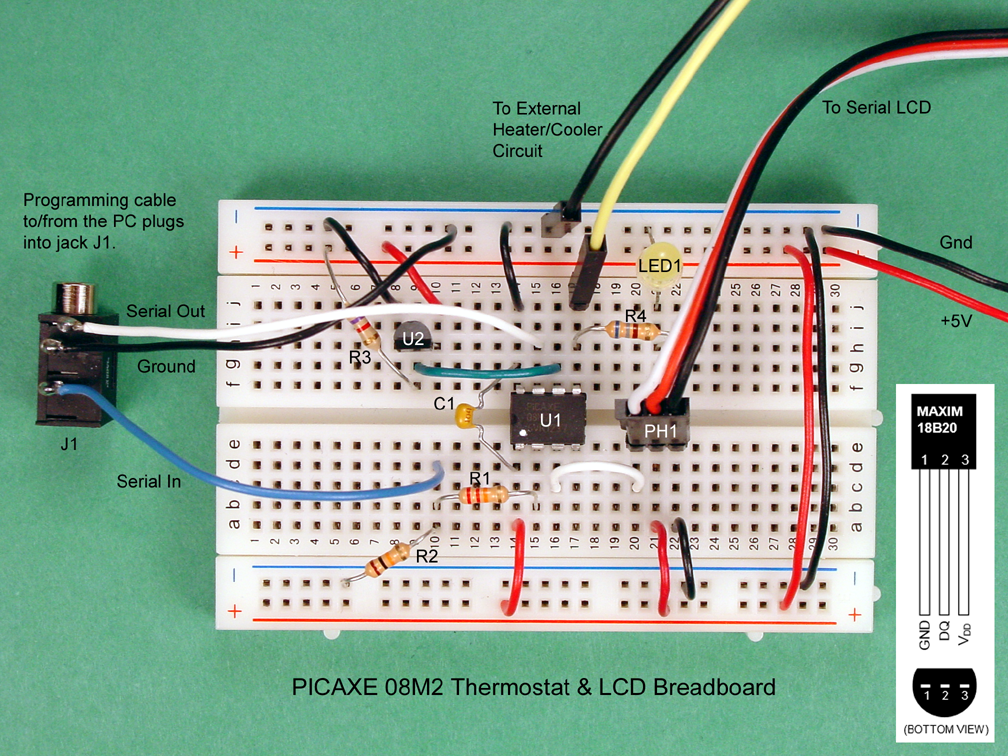
The central part of the hardware required for this project is a microcontroller, and the PICAXE 08M2 is the perfect choice. It's small, powerful, inexpensive, and easy to program, due in part to a built-in command to read the DS18B20 temperature sensor from Maxim. A prior article details exactly how to connect and use these two components together. The photograph below shows the breadboard of the thermostat circuit and includes a pinout diagram for the DS18B20. As you will note, that project displayed the temperature on a Liquid Crystal Display (LCD), but this current project does not require a display.
3.3VDC Power Is Required!
If you are a regular PICAXE user or if you have been following the PICAXE series here on AAC, you know that PICAXE µCs run just fine on 5VDC, and perhaps you also know that the DS18B20 does too. However, this project also uses the ESP8266 IC, which will likely not survive a close encounter with 5V; it must have 3.3V. Fortunately, both the PICAXE 08M2 and the DS18B20 also do fine on 3.3V, so that is what this project uses.
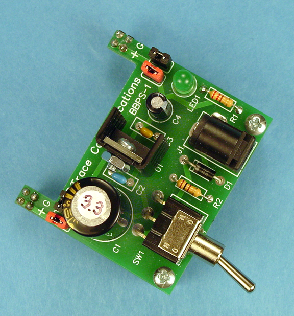
The best power supply choice is a well filtered and regulated, breadboard-friendly 3.3VDC assembly as shown below and described here, or an equivalent. In a pinch, you can use two AA batteries in series, but don't expect long life from them, given the relatively high current consumed by the ESP8266. Whatever you do, don't connect 5V to the ESP8266.
The ESP-01 Module
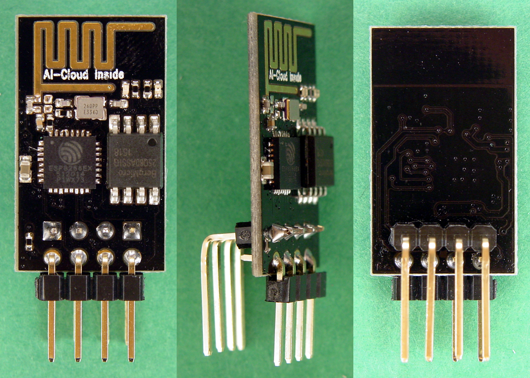
This is the author's third article concerning the ESP8266 integrated circuit, a relatively new chip comprising a full-featured 32-bit RISC µC and a built-in 802.11 b/g/n Wi-Fi circuit. The first article describes using the Arduino IDE to program the ESP8266, and contains instructions for making the ESP-01 module breadboard friendly (as shown in the photo below,) as well as other important background information that will not be repeated here. If you haven't read it, please do.
Most ESP-01 modules don't come with the latest firmware, and should be flashed with updated firmware as described here. This is because the code that you will install in the PICAXE depends upon the ESP-01 being compatible, and there is no guarantee of that unless it contains the correct firmware. Of course, there is no harm in trying to use whatever firmware that your ESP-01 has in it, but don't be surprised if it doesn't work, in which case you will need to update it.
Crucial Change Required to the ESP-01
Whether you decide to upgrade the firmware in your ESP-01 or not, there is one change that is required: changing the baud rate. The command for that in the current firmware is as follows.
AT+UART_DEF=4800,8,1,0,0
Earlier firmware may use the following command.
AT+UART=4800,8,1,0,0
This sets the baud rate to 4800, 8 data bits, 1 stop bit, no parity check, and no flow control. Use PuTTY, Termite, or some other terminal program to make that change. This article provides additional guidance on how to use PuTTY to communicate with the ESP-01.
Putting the Pieces Together
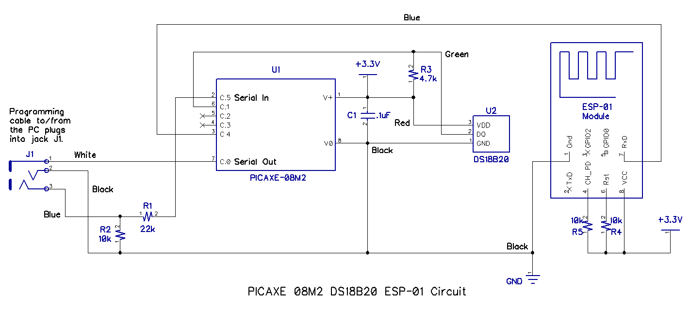
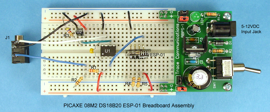
The schematic diagram, a photograph, and a parts list of the final breadboard assembly for the circuit used in this project is shown below. As you see, pin C.4 from the PICAXE is connected to the RxD terminal of the ESP-01 module. No connections are needed to the TxD, GPIO0, or GPIO2 terminals of the ESP-01. Click the images for a larger version.
| Reference No. | Description | Qty. | Source | Part Number |
|---|---|---|---|---|
| J1 | Jack, 3.5mm, 3 Conductor | 1 | Digi-Key | CP1-3533NG-ND |
| R1 | Resistor, .25W, 22kOhms | 1 | Digi-Key | 22KQBK-ND |
| R2. R4. R5 | Resistor, .25W, 10kOhms | 3 | Digi-Key | 10KQBK-ND |
| R3 | Resistor, .25W, 4.7kOhms | 1 | Digi-Key | 4.7KQBK-ND |
| C1 | Capacitor, Ceramic, 50V, .1µF | 1 | Digi-Key | BC2665CT-ND |
| U1 | Microcontroller, PICAXE 08M2 | 1 | P.H. Anderson.com | PICAXE-08M2 |
| U2 | Sensor, Temperature, DS18B20 | 1 | Digi-Key | DS18B20+-ND |
| N/A | Power Supply, 3.3VDC, Regulated & Filtered | 1 | See text. | See text. |
| N/A | Cable, PICAXE, Programming, USB | 1 | P.H. Anderson.com | AXE027 |
| N/A | Breadboard, Solderless | 1 | Digi-Key | 377-2094-ND |
| N/A | Module, ESP-01, Modified to Be Breadboard-Friendly | 1 | on-line search | ESP-01 |
| N/A | Wire, Jumper, AWG22, Solid, Tinned, Asstd. Colors | N/A | Jameco | 2153705 |
Thingspeak
If you don't already have an account at Thingspeak, go there and follow the directions to open one.
Thingspeak allows you to create "channels" for your projects, and the process for creating a channel is described in a tutorial. Unfortunately, the tutorial is written around using an Arduino, but just ignore those references. After that, it's really quite simple as shown in the snips from their web site shown below.
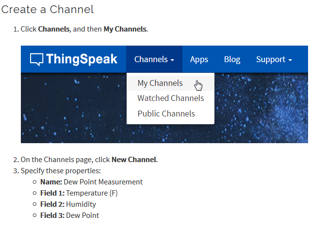
Note that the entries above are just examples; fill in the blanks with information applicable to your project for this channel. For "Name," enter "My Room Temp" or something similar. For "Field 1," enter "Temperature (C)". One field is all you will need for this project. Information for the other fields is optional.
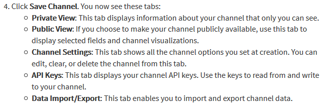
The most important bits of information at this point are the "API Keys." They are 16-digit sequences of letters and numerals that are essential to uploading data (the write key) and downloading data (the read key.) This project requires you to use the write key, but at some point you will need the read key as well; write them both down exactly as they appear on the screen. There is lots more to learn on the Thingspeak web site, but it can wait until later.
The PICAXE Code
The code for this project is displayed below; it is neither sophisticated nor elegant, but it is functional. It was written to be as straighforward and uncomplicated as possible and still perform its intended function. It is well commented and should be easily understood. Although it works reliably for the author, the code is not to be used for any "mission critical" applications, and is only suitable for hobbyist and experimenter use.
As you see below, the code uses a series of commands from the PICAXE to direct the ESP-01 to communicate with Thingspeak. These commands are based on the AT Command Set, and are documented here. The code is "blind" because it sends commands, but does not "watch" for responses. Instead, it pauses for some period of time to allow the command to be sent and for the ESP-01 and/or Thingspeak to have time to react. The times for the pauses have been determined based on experimentation; your wireless LAN and internet connection speed may operate faster or slower. If your setup is faster, the code will still run as is, but if your setup is slower, you may have to lengthen some or all of the pause times.
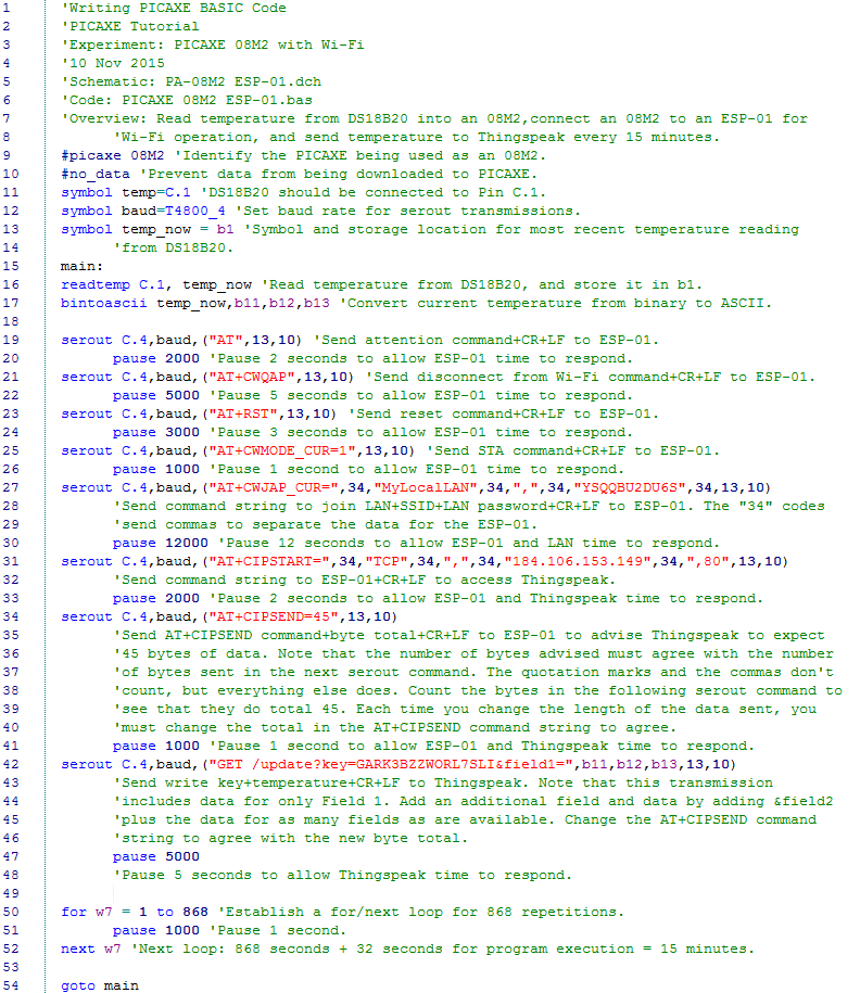
PICAXE_08M2_ESP-01_redacted.zip
There are two changes that are required to the code before trying to run it.
First, in line 27, you must enter the SSID for your LAN, and the password for it. Be certain to put it between the quotation marks as shown above. Do not make any other changes in line 27.
Second, in line 42, you must enter the write key for your channel at Thingspeak, which will be a combination of 16 chararacters and numerals. Be certain to put it between the equal sign and the ampersand as shown above. Do not make any other changes in line 42.
Now, you can program the PICAXE 08M2, and watch for results on Thingspeak.
Next...
Hopefully, you now have your own temperature reader working and dutifully reporting the temperature every 15 minutes to Thingspeak. If not, first recheck your hardware against the schematic drawing and/or the breadboard photograph. Next, recheck the changes you made to the code to enter your SSID, password, and Thingspeak write key; any extra characters or spaces or deletions will foul the operation. Be sure you have the baud rate in the ESP-01 set as directed above. If you did not previously update the firmware in the ESP-01, do that now.
Once you have it working, the sky is the limit. Save a copy of the basic code that works for you, and then on another copy, make changes to see how you can improve it.
Happy tinkering!
Give this project a try for yourself! Get the BOM.