This article covers the essential characteristics and prominent advantages of the inter–integrated circuit (AKA I2C) serial-communications protocol.
Communication Between Components: Communication Protocols
It should come as no surprise that a common feature of electronic systems is the need to share information among two or three or ten separate components.
Engineers have developed a number of standard protocols that help different chips communicate successfully—a fact that becomes apparent when you confront the barrage of acronyms under “communications” in the list of features for a microcontroller or digital signal processor: UART, USART, SPI, I2C, CAN. . . . Each protocol has its pros and cons, and it is important to know a little about each one so that you can make an informed decision when choosing components or interfaces.
This article is about I2C, which is typically used for communications between individual integrated circuits located on the same PCB. Two other common protocols that also fit into this general category are UART (Universal Asynchronous Receiver/Transmitter) and SPI (Serial Peripheral Interface). You need to know the basic characteristics of I2C before you can thoroughly understand a comparison between these three interfaces, so we will discuss that topic at the end of this article.
What Is the I2C Bus?
I2C stands for inter–integrated circuit bus. There is no doubt, though, that the I2C protocol suffers from a serious terminology problem. The most straightforward—and probably the least common—abbreviation is IIC. Perhaps this abbreviation has been disdained because the two capital I’s look like two 1s, or two lowercase l’s, or Roman numeral II, or the symbol for parallel resistors. . . . In any event, the abbreviation I2C (spoken as “I squared C”) gained popularity, despite the questionable logic of treating a normal letter as if it is a variable subject to exponentiation. The third option is I2C (“I two C”), which avoids the inconvenience of superscript formatting and is also somewhat easier to pronounce than “I squared C.”
The final layer of fog settles in when you notice that SMB or SMBus is apparently used as yet another way of referring to the I2C bus. Actually, these abbreviations refer to the System Management Bus, which is distinct from, though almost identical to, the I2C bus. The original I2C protocol was developed by Phillips Semiconductor, and years later Intel defined the SMBus protocol as an extension of I2C. The two buses are largely interchangeable; if you are interested in the minor differences between them, refer to page 57 of the System Management Bus Specification.
Like Trying to Have an Important Conversation in a Room Full of People
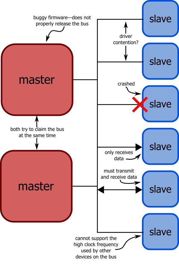
To appreciate the clever techniques that make I2C so effective, you need to think about the difficulty of achieving reliable yet versatile communication between multiple independent components. The situation is simple enough if you have one chip that is always the master and one chip that is always the slave.
But what if you have multiple slaves? What if the slaves don’t know who the master is? What if there are multiple masters? What happens if a master requests data from a slave that for some reason has become nonfunctional? Or what if the slave becomes nonfunctional in the middle of a transmission? What if a master claims the bus to make a transmission then crashes before releasing the bus?

The point is, there are a lot of things that can go wrong in this sort of communication environment. You have to keep this in mind when you are learning about I2C because, otherwise, the protocol will seem insufferably complicated and finicky. The fact is, this extra complexity is what allows I2C to provide flexible, extensible, robust, low-pin-count serial communication.
Overview of I2C Communication
Before we get into any details, here are the key characteristics of I2C:

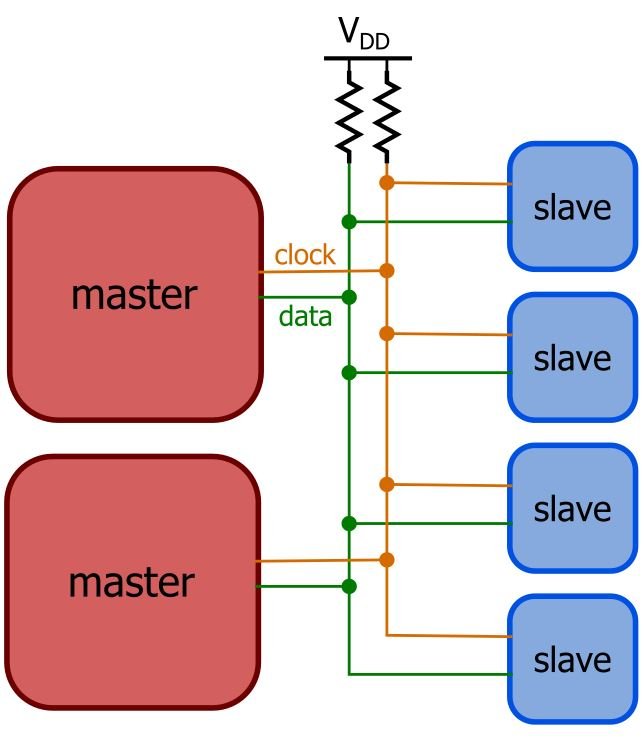
- Only two signals (clock and data) are used, regardless of how many devices are on the bus.
- Both signals are pulled up to a positive power supply voltage through appropriately sized resistors.
- Every device interfaces to the clock and data signal through open-drain (or open-collector) output drivers.
- Each slave device is identified by means of a 7-bit address; the master must know these addresses in order to communicate with a particular slave.
- All transmissions are initiated and terminated by a master; the master can write data to one or more slaves or request data from a slave.
- The labels “master” and “slave” are inherently non-permanent: any device can function as a master or slave if it incorporates the necessary hardware and/or firmware. In practice, though, embedded systems often adopt an architecture in which one master sends commands to or gathers data from multiple slaves.
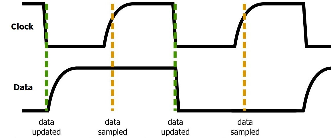
- The data signal is updated on the falling edge of the clock signal and sampled on the rising edge, as follows:

- Data is transferred in one-byte sections, with each byte followed by a one-bit handshaking signal referred to as the ACK/NACK (acknowledge or not-acknowledge) bit.
What Are the Advantages of I2C? I2C vs UART vs SPI
The advantages of I2C can be summarized as follows:
- maintains low pin/signal count even with numerous devices on the bus
- adapts to the needs of different slave devices
- readily supports multiple masters
- incorporates ACK/NACK functionality for improved error handling
And here are some disadvantages:
- increases the complexity of firmware or low-level hardware
- imposes protocol overhead that reduces throughput
- requires pull-up resistors, which
- limit clock speed
- consume valuable PCB real estate in extremely space-constrained systems
- increase power dissipation
We can see from these points that I2C is especially suitable when you have a complicated, diverse, or extensive network of communicating devices. UART interfaces are generally used for point-to-point connections because there is no standard way of addressing different devices or sharing pins. SPI is great when you have one master and a few slaves, but each slave requires a separate “slave select” signal, leading to high pin count and routing difficulties when numerous devices are on the bus. And SPI is awkward when you need to support multiple masters.
You may need to intentionally avoid I2C if throughput is a dominant concern; SPI supports higher clock frequencies and minimizes overhead. Also, the low-level hardware design for SPI (or UART) is much simpler, so if you are working with an FPGA and developing your serial interface from scratch, I2C should probably be considered a last resort.
Conclusion
We have presented the salient characteristics of I2C, and we now know enough about the protocol’s pros and cons to allow for an informed decision on which serial bus you might choose for a given application. In future articles we will explore the protocol, and how to actually implement it, in more detail.
