A new highly accurate cold chain digital temperature sensor from ams makes the design of refrigerators and data loggers, in cold-chain storage equipment, a little easier.
The AS6200C is a high-performance and highly accurate cold chain digital temperature sensor. Available only in an extremely small 6-pin, 1.5 × 1 mm WLCSP package (see figure below), this "easy-to-use" (according to ams) temperature-sensing solution requires no user calibration or linearization, uses an I2C interface, and provides 12 bits of resolution.
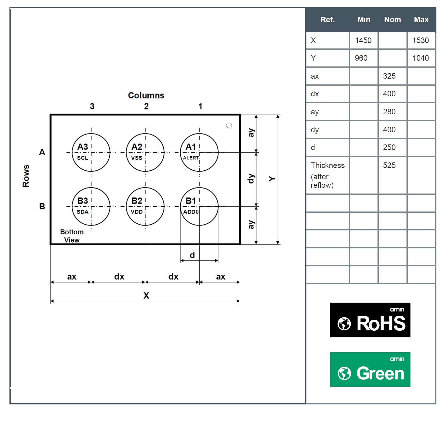
The AS6200C is available only in a minuscule wafer level chip scale package. Drawing taken from the datasheet.
And speaking of the I2C interface, the AS6200C's I2C bus speed is limited to 400 kHz...unless a “high speed command” is issued by the master device (e.g., the microcontroller to which this IC is connected). Once the “high speed command” is issued, the device can support data transfer frequencies up to 3.4 MHz. Check out section 6.3.9 (entitled High Speed Mode) in the datasheet for more information.
One final comment regarding the I2C interface: if your design calls for more than one of these digital temperature sensors, simply add a second device to the same I2C bus and then use the IC's ADD0 pin to assign a different I2C address (see the figure below).
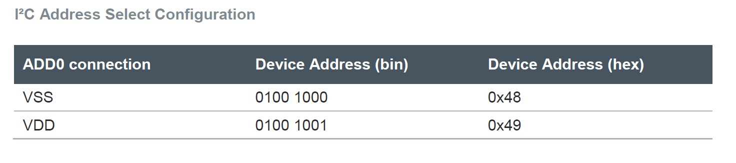
The AS6200C's ADD0 pin can be used to create different I2C addresses. Table taken from the datasheet.
Measurement Accuracy
This temperature sensor offers an impressive automotive-grade operating temperature range, which is from -40°C to 125°C, but keep in mind that the optimal accuracy (±0.2°C) is valid only from -10°C to 20°C. The temperature accuracy is still quite good when operating in temperatures from -20°C to 65°C, but beyond this range it jumps to ±1°C. See the figure below for detailed information on the AS6200C's accuracy specs.
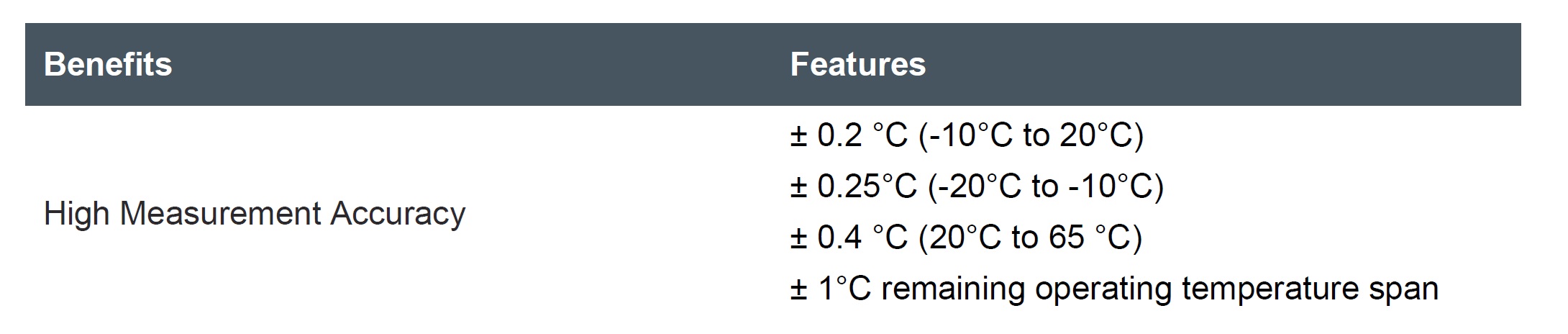
As noted in the datasheet, the IC's temperature measurement accuracy varies as a function of temperature.
Power Consumption
As stated in the datasheet, this "ultra-low" power consumption device is "ideally suited for mobile/battery powered applications," but be mindful that current consumption is influenced by the rate at which the device is performing temperature measurements. The supply-current specs given in the datasheet (i.e., 6 µA typical) assume 4 conversions per second, which is probably adequate for most of the intended applications; the chip’s maximum rate in continuous mode, as opposed to single-shot mode (see below), is 8 conversions per second. Lower rates correspond to lower current consumption because the device is active only during an actual conversion procedure, as depicted in the following diagram (“TS” is the conversion time, which is typically 32 ms).
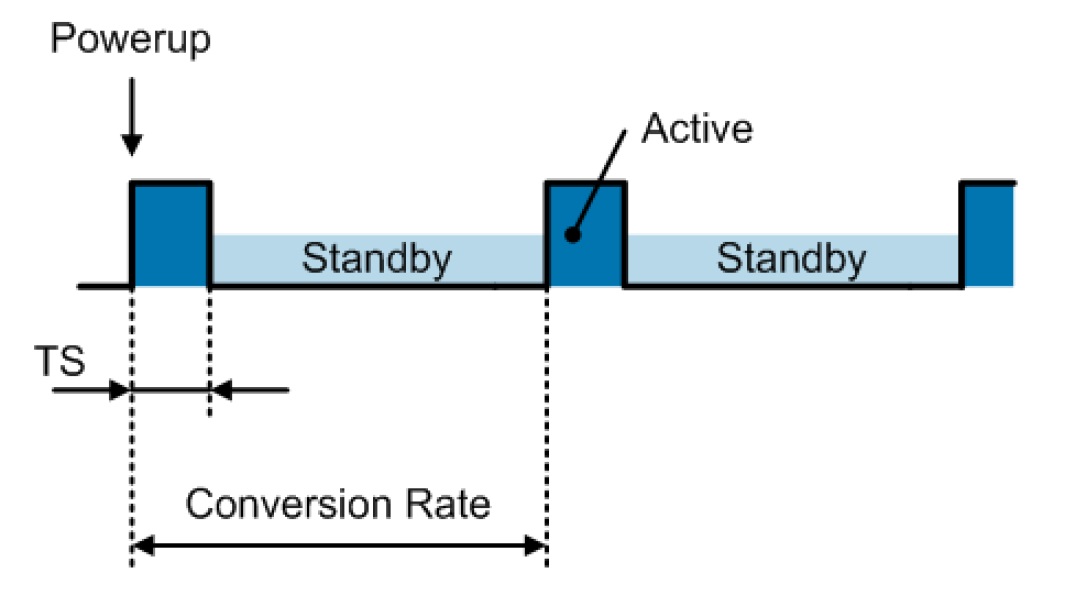
Higher-frequency conversions require more current because the chip spends more time in active mode. Diagram taken from the datasheet.
If you really need to minimize power consumption, you can use single-shot mode (see Section 6.2.8 in the datasheet), which allows you to initiate conversions on an "as-needed" basis.
Single-shot mode is also handy if you are determined to get more than 8 measurements per second. Since the AS6200C's typical conversion time is only 32 ms, you could theoretically push the conversion rate up toward 30 Hz. But you should avoid higher rates whenever possible, not only to conserve battery life but also because the higher power dissipation will increase the temperature of the chip relative to the surrounding environment.
Converting between Binary Data and Degrees Celsius
The measured temperature is represented as a two's complement value, since both positive and negative temperature values are measured. See page 22 in the datasheet for additional information on converting from temperature to binary.
One detail to keep in mind is that after power-up the temperature value will remain at 0°C until the first conversion has been completed.
Resistors and a Cap
A typical circuit is shown below. Let all readers take note that the AS6200C datasheet does not explicitly recommend the legendary 100 nF decoupling-cap value. The datasheet merely says that the minimum value is 10 nF. However, since that’s a bit vague, the safest bet is to stay with 100 nF. Also, ams demonstrates some solid attention to detail by noting that the designer should consider the bus characteristics when choosing the value for the I2C pull-up resistors (see this app note for more information).
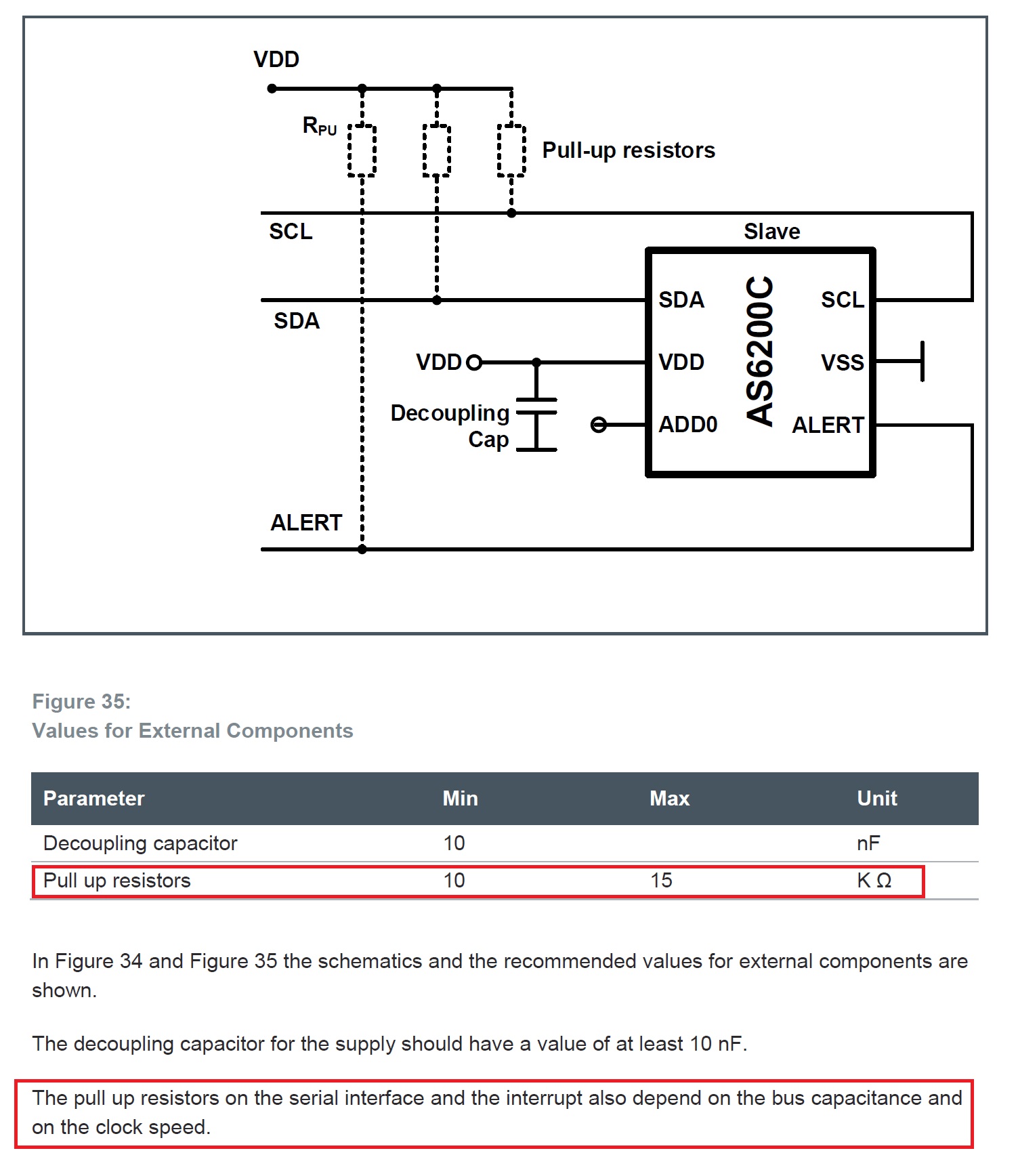
Information on the external components, from the datasheet.
Have you had an opportunity to use this cold chain digital temperature sensor in any of your designs? If so, leave a comment and tell us about your experiences.
Featured image used courtesy of ams.