Most electronic components dissipate heat whenever a current flows through them. The amount of heat depends on the power, device characteristics, and circuit design. Besides the components, the resistance of the electrical connections, copper traces, and vias contribute to some heat, and power losses.
To avoid failures or circuit malfunctions, designers should aim at producing PCBs that operate and remain within safe temperature limits. While some circuits will work without additional cooling, there are situations where adding heat sinks, cooling fans, or a combination of several mechanisms is inevitable.
This article will discuss design practices that ensure better thermal management, including some common methods for removing excess heat from a PCB.

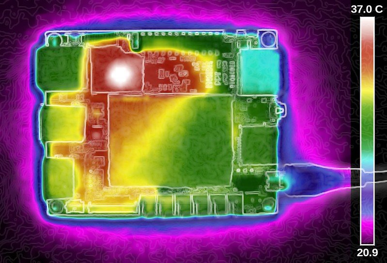
A themal image of a LattePanda single-board computer. Image by Gareth Halfacree. [CC BY-SA 2.0]
Good PCB Design Practices
Major issues to consider during design are:
- Performance data and dimensions of the components
- Major heat-dissipating components
- Size of the PCB
- PCB material, layout, and component placement
- Mounting peripherals
- Temperature of the application environment
- Amount of heat dissipated
- Appropriate cooling methods, i.e., cooling fans, heat sink, etc.
A best practice is to manage the temperature at the component and system level while considering the operating environment. Factors to consider when deciding on a cooling mechanism include the package properties of the semiconductor, heat dissipation properties, etc. This information is usually available from the manufacturer’s datasheet.
Natural convection cooling is adequate for PCBs with small amounts of heat dissipation. However, PCBs with excess heat require heat sinks, heat pipes, fans, thick copper or a combination of several cooling techniques.
Reduce Thermal Resistance
A low thermal resistance ensures that the heat is transferred through the material much faster. This resistance is directly proportional to the length of the thermal path and inversely proportional to the cross-sectional area and thermal conductivity of the thermal path.
Thermal resistance
Where
- t is the thickness of the material
- K is the thermal conductivity factor
- A is the cross-sectional area
Designers often reduce thermal resistance by:
- Using a thinner PCB to reduce the thermal path
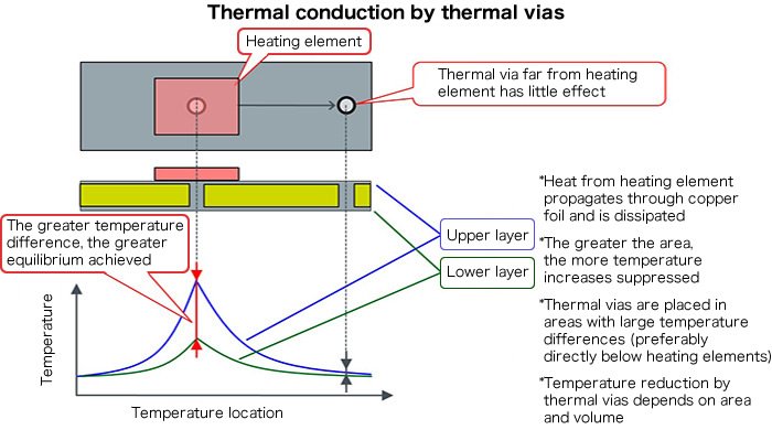
- Adding thermal vias for vertical heat conduction
- Copper foil and thick tracks for horizontal heat conduction

An overview of thermal conduction by thermal vias. Image used courtesy of ROHM Semiconductor
Identify Components with the Potential to Dissipate More Heat
It is important to understand which components generate the most heat and decide on the best removal mechanism. Using the manufacturer's datasheet, a designer should find out the thermal rating and characteristics of the device. Most often, the manufacturers will provide guidelines on how to remove excess heat.
Consider Component Placement, Orientation, and Organization
Components that dissipate more power should be located in areas providing the best heat removal. This should not be at the corners or edges of the PCB unless there is a heat sink. Placing components somewhere near the middle ensures heat dissipation around the device, however, there should be enough space for adequate air circulation.
Although it may be difficult to ensure an even temperature distribution, it is important to avoid concentrating the high power components together. Distributing them evenly prevents hot spots.
Another good practice is to place sensitive components such as small ICs, transistors, and electrolytic capacitors in low-temperature areas. In circuits that rely on convection cooling, arranging components such as ICs in a horizontal or vertical long manner helps in thermal management.
How to Identify Thermal Problems with Your PCB
Designers can use a wide range of techniques to identify potential problems. Popular approaches include the use of thermal analysis tools, visual inspections, and infrared cameras.
Conduct Thermal Analysis
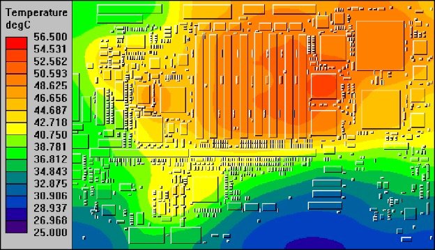
Performing a thermal analysis establishes how the components and PCB will behave at different temperatures and conditions. The analysis provides designers with an idea of the heat generation and transfer within the circuit.
Designers can then use analysis results and simulations to come up with techniques that will help them better manage the heat.

PCB thermal analysis. Image Courtesy of PADS
Visually Inspect the Board without Power
Visual inspection is an easy way to find signs of overheating, burnt or partly damaged components, dry joints, arcing, etc. Some of the visible signs include bulging components, burnt components, and discolored spots on the PCB. In addition to the visual analysis, a smell from the board can also point to heating issues.
Use Infrared Cameras
Test engineers can use IR cameras to evaluate powered prototype boards for heat problems and identify issues invisible to the naked eye. In addition to showing areas where there is excess heat, the cameras can sometimes identify counterfeit or defective parts whose thermal signatures differ from those of genuine components.
Thermal imaging cameras can also detect the location where the tracks have insufficient solder, hence higher resistance and more heat dissipation.
How to Remove Heat from Circuit Boards
There are several techniques that designers can use to remove heat from components and PCBs. The common mechanisms include heat sinks, cooling fans, heat pipes, and thick copper. Most often, circuits generating more heat require more than one technology. For example, cooling a laptop processor and display chips requires a heat sink, heat pipe, and a fan.
Heat Sinks and Cooling Fans
A heat sink is a thermally conductive metallic part with a large surface area, usually attached to components such as power transistors and switching devices. A heat sink allows the component to dissipate its heat over a larger area and transfer that heat to the surroundings. In some cases, such as high current power supplies, adding a cooling fan aids in faster and better heat removal.
Heat Pipes
Heat pipes are suitable for compact devices with limited space. The pipes provide a reliable and cost-effective passive heat transfer. Benefits include a vibration-free operation, good thermal conductivity, low maintenance, and quiet operation since they have no moving parts.
A typical pipe contains small amounts of nitrogen, water, acetone, or Ammonia. These fluids help to absorb the heat, upon which they release a vapor that travels along the pipe. The pipe has a condenser where, as the vapor passes through, it condenses back to its liquid form and the cycle begins again.
Thermal Via Arrays
Thermal vias increase the mass and area of the copper, reducing the thermal resistance and improving heat dissipation from the critical components through conduction. As such, better performance is achieved when the vias are placed closer to the heat source.
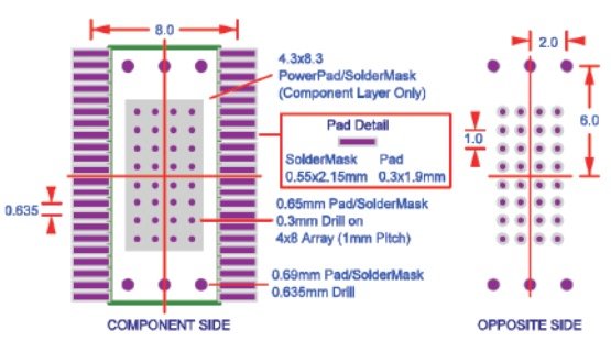
In some applications, heat from a device, such as a thermally optimized IC, is conducted away through the combination of a thermal via array and pad. This eliminates the need for a heat sink while improving the heat dissipation through the PCB.

Thermal via array. Image used courtesy of Texas Instruments
Thick Copper Traces
Using more copper provides a larger surface area that helps in heat distribution and dissipation. Such PCBs are suitable for high power applications.
Conclusion
PCB thermal management techniques depend on a number of factors including the amount of heat the components and circuit dissipate, the environment, the overall design, and the enclosure. If heat generation is low, the circuit can work without additional cooling. However, if the circuit generates higher amounts of heat, there should be a cooling mechanism to take away the heat.
To provide thermally optimized PCBs, designers should consider everything that influences temperature right from the concept stage and throughout the design and manufacturing stages.
